Mini Tesla Coil
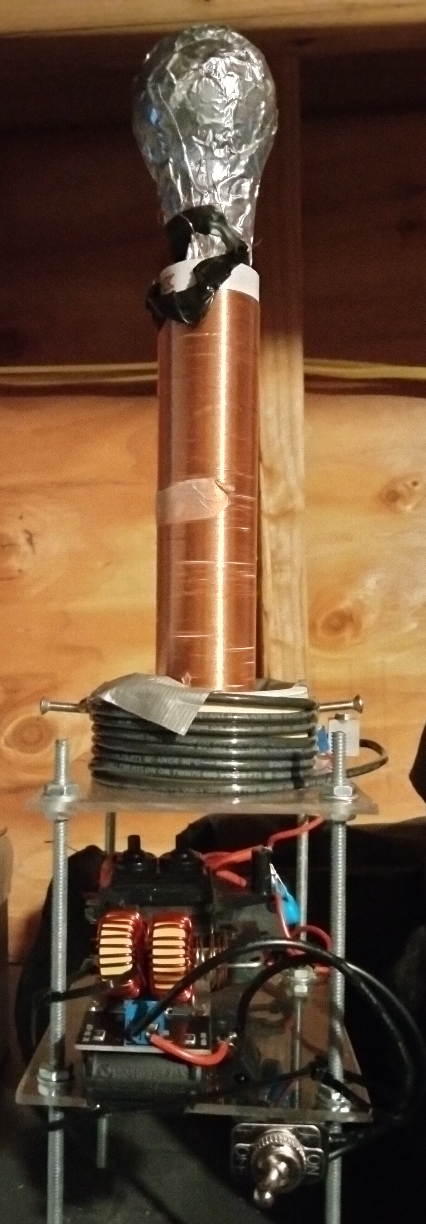
As an introduction to the world of high voltage engineering, I decided to dive head first into the subject by building a miniature spark-gap tesla coil. It has a 13.875cm long secondary coil, 1.67cm in diameter, with about 450 turns. The primary has around 7 3/4 turns of 14 guage house wire, ~6.75 cm in diameter. The secondary tank circuit has a measured resonance frequency of 1.13 MHz, with an old lightbulb covered in aluminum tape acting as a capacitor. The primary uses a CRT flyback that I got off ebay as a power supply, and 2 1nf capacitors in series for a primary tank capacitance of 2nf. This endeavor has taken me a lot (insert emphasis here) of time, a lot more than it should have. This is partially due to my horrible planning skills, as well as a procrastinating nature and occasional lack of motivation. It should also be noted that this project was, again, a learning experience, and so I did end up making a lot of modifications and complete reworks several times. However, after nearly five months of sluggish progress, I think I am in a place where I can confidently say that the project is finished.
Theory of Operation
A tesla coil is essentially a high voltage transformer whose secondary and primary tank circuits have the same resonance frequency. A tank (or LC) circuit is simply an electrical oscillator that uses a capacitor and an inductor to generate sinusoidinal electrical signals. In a tesla coil, both the primary and secondary are a part of their own, seperate tank circuits. However, in a tesla coil, the frequency of these oscillations (the resonance frequency), is equivalent (ideally). This is done by choosing appropriate tank capacitor values in both circuits. When the primary and secondary have the same resonance frequency, they will resonate with another. This allows for the most efficient setup possible, with no energy losses due to differing phases. All Tesla coils require high voltage power supplies for their primary circuits, as the secondary to primary turn ratio only steps up the voltage so much. In this coil, a CRT flyback was used, with an output of around 5Kv at a max current of around 10mA.
Design
Secondary Coil
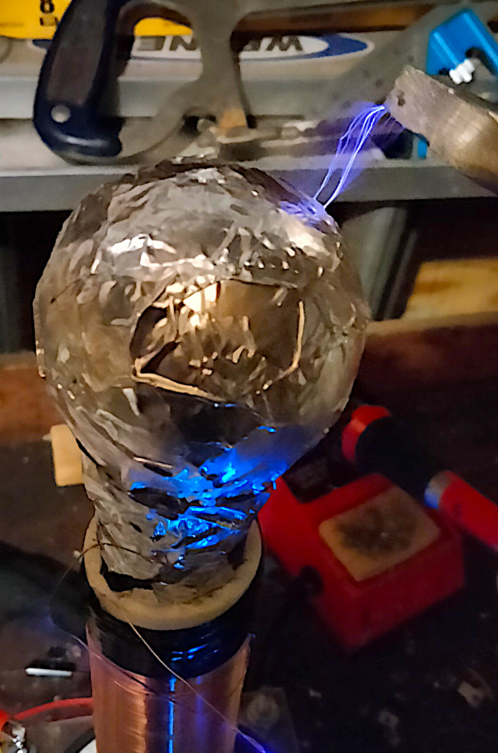
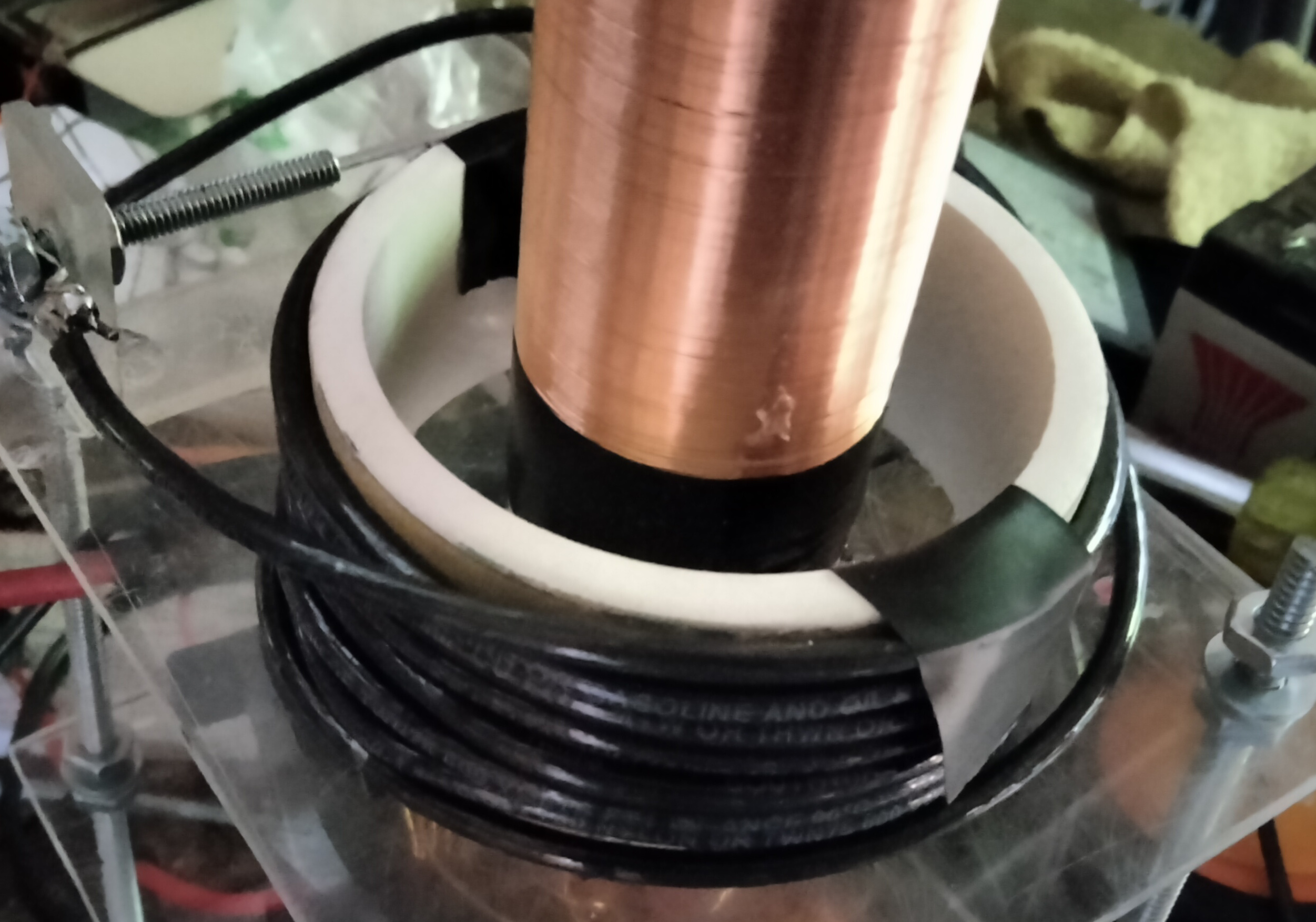
The secondary coil is constructed from a 1.67cm radius PVC pipe with 13.875cm of windings of 28AWG wire for a grand total of ~475 windings. In series with the top-load, which is an old lightbulb covered in aluminum tape in my case, acts as the secondary tank capacitor. By looking hooking up an oscilloscope to the secondary circuit and supplying a waveform of a certain frequency, by changing said frequency I was able to identify what the resonance frequency was (1.13 MHz) by visually identifying which frequency gave the sine waves with the largest amplitude on the oscilloscope. Based off of this data, I was able to improve the size of my arcs by a tangible amount, although not enough for my satisfaction. It is worth noting that the resonance frequency that was measured did not align with the value that JavaTC gave me, probably due to the sketchy nature of this coil.
Primary Coil
Primary coil
I actually ended up making several primaries throughout this project (trial and error, right?), so I have chosen to document the version that I used with the final product. The primary is made out of 14awg insulated house electrical wire wound around a 6.75cm diameter PVC pipe. In order to get the Primary to resonate with the secondary, we need to figure out the inductance of the primary. To do this, I used an online calculator, which is a lot easier than doing the calculations by hand. From there, by using the equation for the frequency of an LC circuit, which states that f = 1/2pi*sqrt(LC), it is just a matter of using simple algebra to find C, the capacitance of the primary tank capacitor. For my primary, this was 2.2nF. I ended up just soldering two 1nF 30kV ceramic capacitors in series, which isn't super precise, but thanks to my adjustable grounding connecter, small adjustments of the primary coil can adjust for this.
Spark Gap
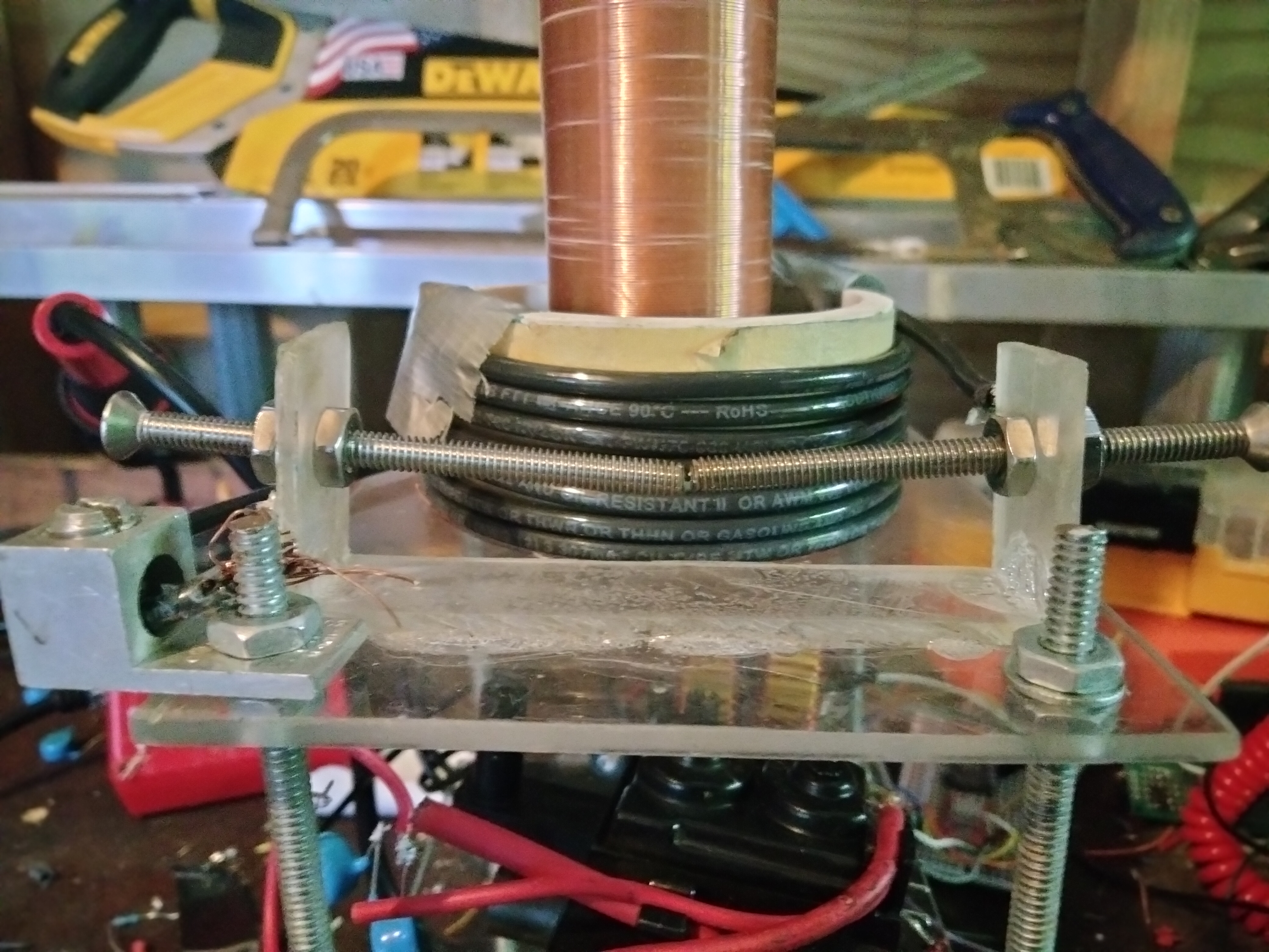
Spark gap
The spark gap was constructed by using two small steel screws threaded through a plexiglass bracket. One screw was connected to an end of the primary coil, the other end of which was grounded, and the other screw was hooked up to the end of the capacitor bank. When the voltage got high enough, an arc would break between the two screws, allowing the capacitors to discharge to the ground through the primary coil, producing the necessary electromagnetic fields to induce a voltage in the secondary. However, this system had an absolutely massive flaw, known as quenching. Due to the nature of CRTs, the arcs that would form in the spark gap would superheat the air, ionizing it and producing an ion "bridge" with very little resistance, preventing the capacitors from charging and leading to a constant flow of electricity through the circuit in the form of a small arc between the terminals. Quenching is a very important topic regarding Tesla Coils, although it is usually not as prevalent amongst traditional NST/MOT powered coils. This was not apparent to me, and so you would have to blow on the coil or run a fan right next to it in order for it to work proprely.
Capacitor Bank
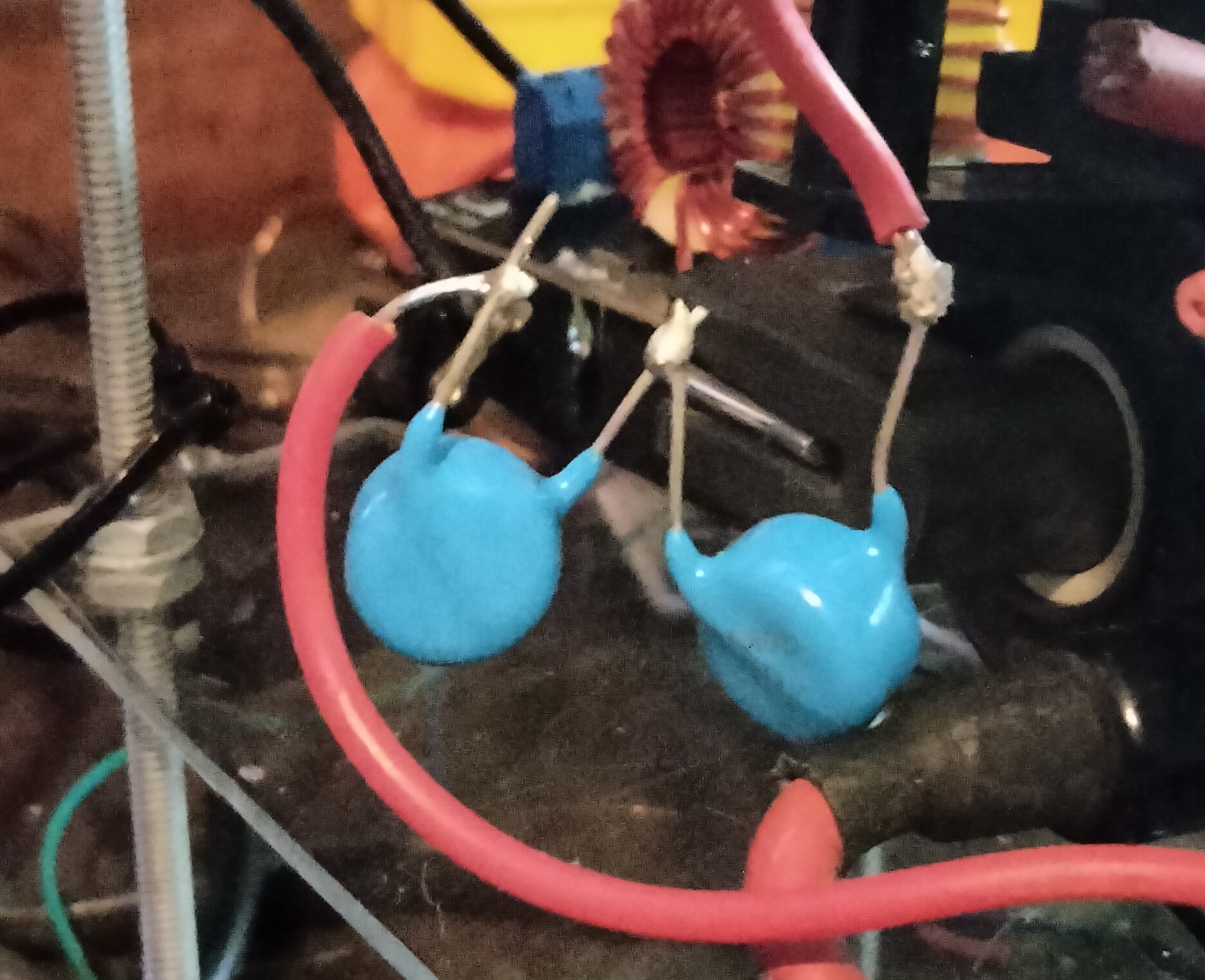
Capacitor Bank
I ended up going through several variations of capacitor banks, but ended up settling on using 2 1nF 20kV ceramic capacitors in series. The previous attempt used an array of 2.2nF capacitors to match the measured capacitance required for the optimal tuning of the coil, but they were far too weak and ended up dying in a pungent display of smoke. The 2nF setup seemed to produce the greatest arcs, and although wasn't extremely tuned to the secondary circuit, it produced the best results. Regardless, if the proper capacitors had been used and the primary circuit properly tuned to the secondary circuit, the arcs that I recieved would have been massively impproved, potentially even doubling in size.
Power Supply
The power supply is the heart and lungs of this tesla coil. I ended up settling on using a CRT flyback and a ZVS driver, giving upwards of 20,000 volts, although at a low enough current that I wasn't absolutely terrified of it (around a few mA). A new secondary was wound around the transformer, and hooked up to a ZVS driver that I got off Amazon. An attempt was made to make my own ZVS driver, but poor soldering skills and logistical errors got in the way, leading to me throwing in the towl and just buying one.
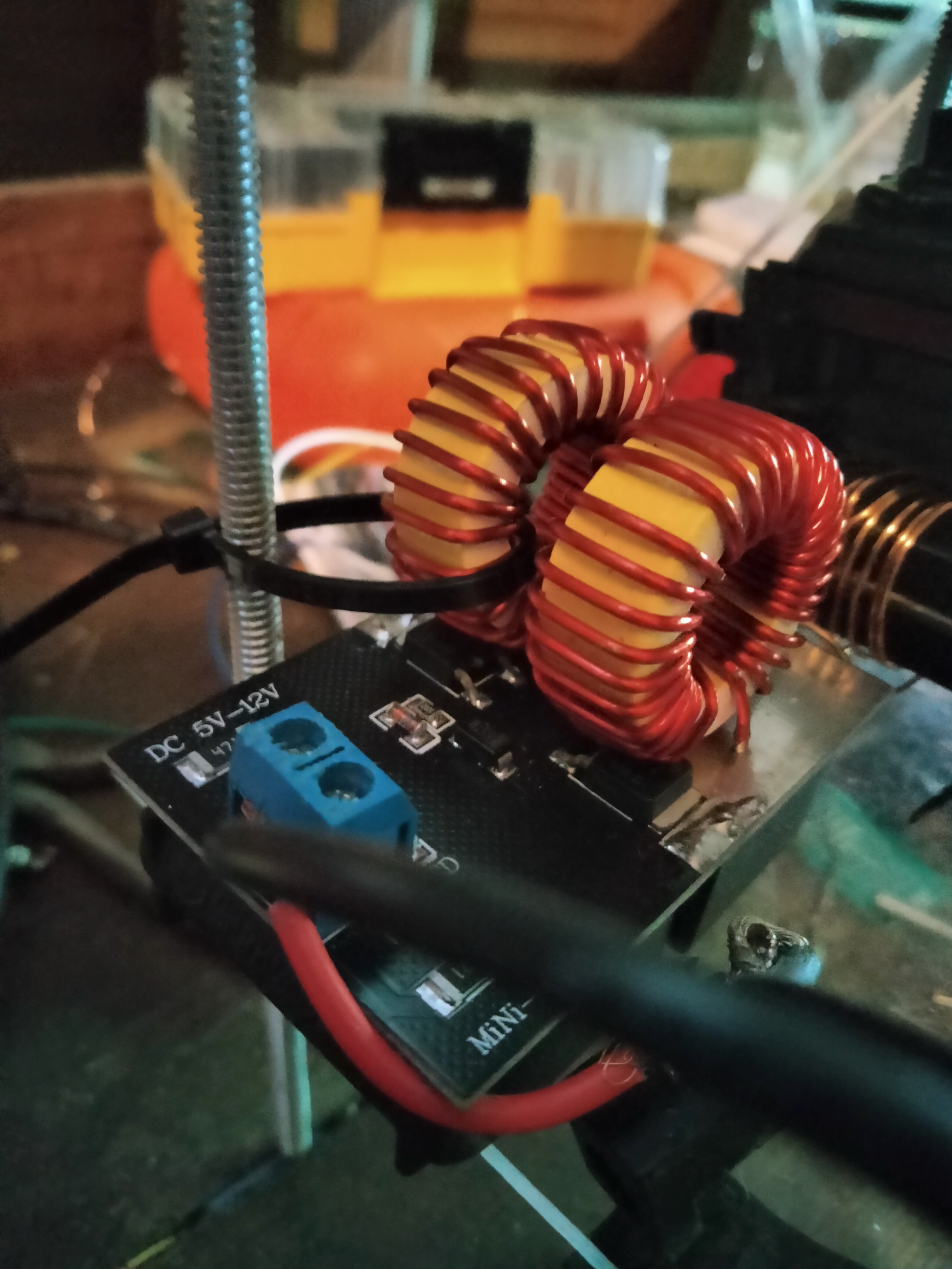
ZVS driver
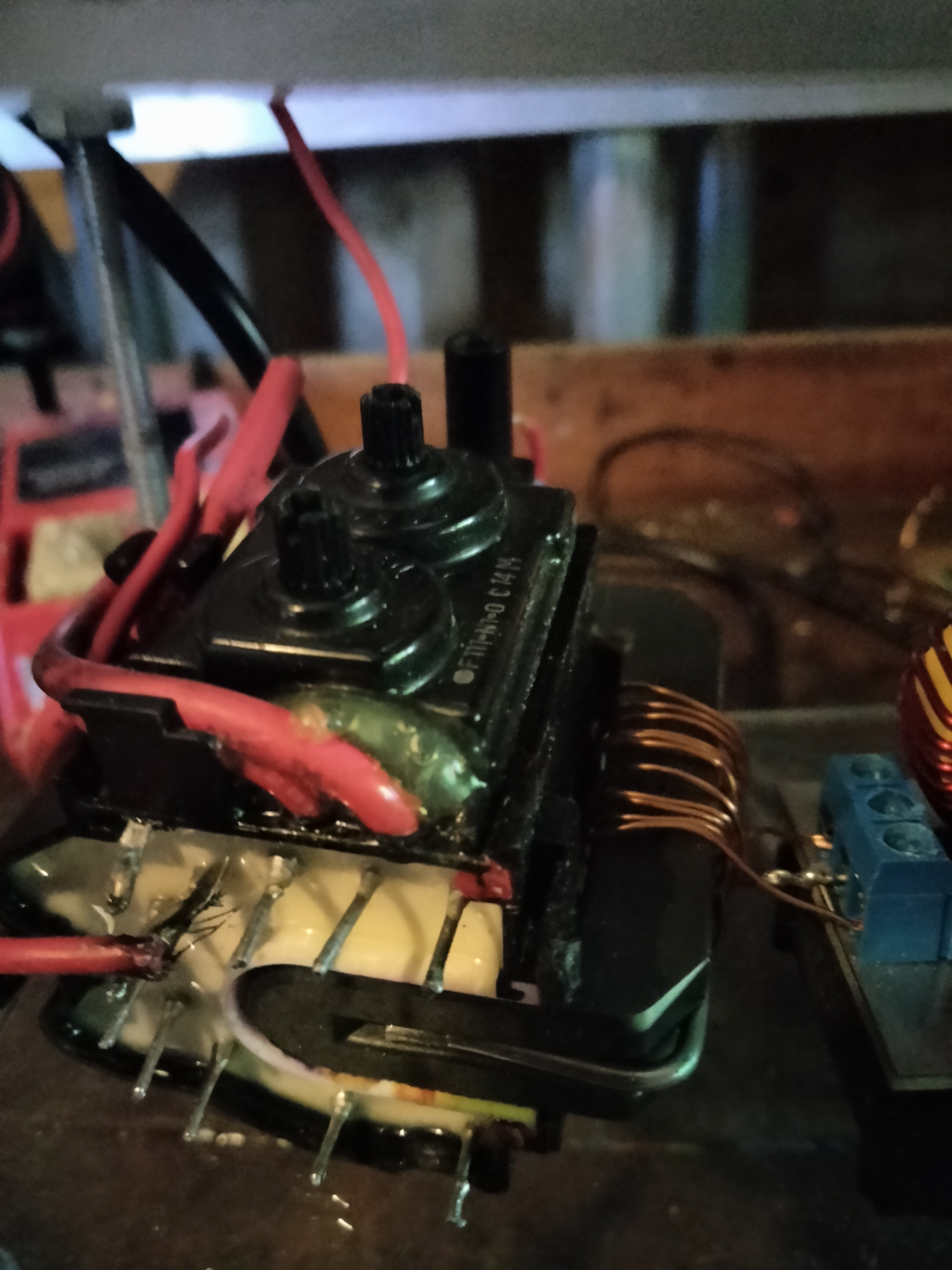
CRT flyback
To prepare the CRT flyback, a center-tapped primary coil was wound using (22?) guage wire around the ferrite core of the transformer. The ground pin of the CRT was hooked up to one of the bolts holding the stand together.
Conclusion
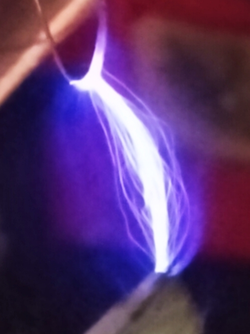
This miniature tesla coil isn't very powerful at all, and it isn't very well thought out; that being said, it is my first project in the realm of high voltage fun/insanity/time-wasting-life-risking-stupidity. The whole thing isn't very well tuned, it looks kind of ugly (an understandment, to be honest), it doesn't have any proper spark gap quenching, and it isn't safe to touch for some reason (found that one out the hard way). However, it can make some fun little arcs, and create some pretty cool plasma inside of a lightbulb. During some of my better runs of the thing, I would get streamers about a centimeter or so in length coming out of a nail that was placed on the topload. One potential source of error, most likely on my part, is the discrepancy between my calculations/data and what JavaTC, a popular tesla coil calcuator website, was giving me. For example, the secondary tank circuit frequency that JavaTC was giving me was drastically different than what I was getting. It also wasn't giving me accurate numbers on the resonance frequency of my primary circuit, another area of concern (in hindsight, this is probably due to my disregard of the mutual inductance between the primary and secondary coils, which would have altered resonant frequencies a bit). In the end, this thing is an honest to god tesla coil, a true self-resonating circuit, and is pretty cool in that sense.