Spark Gap Tesla Coil
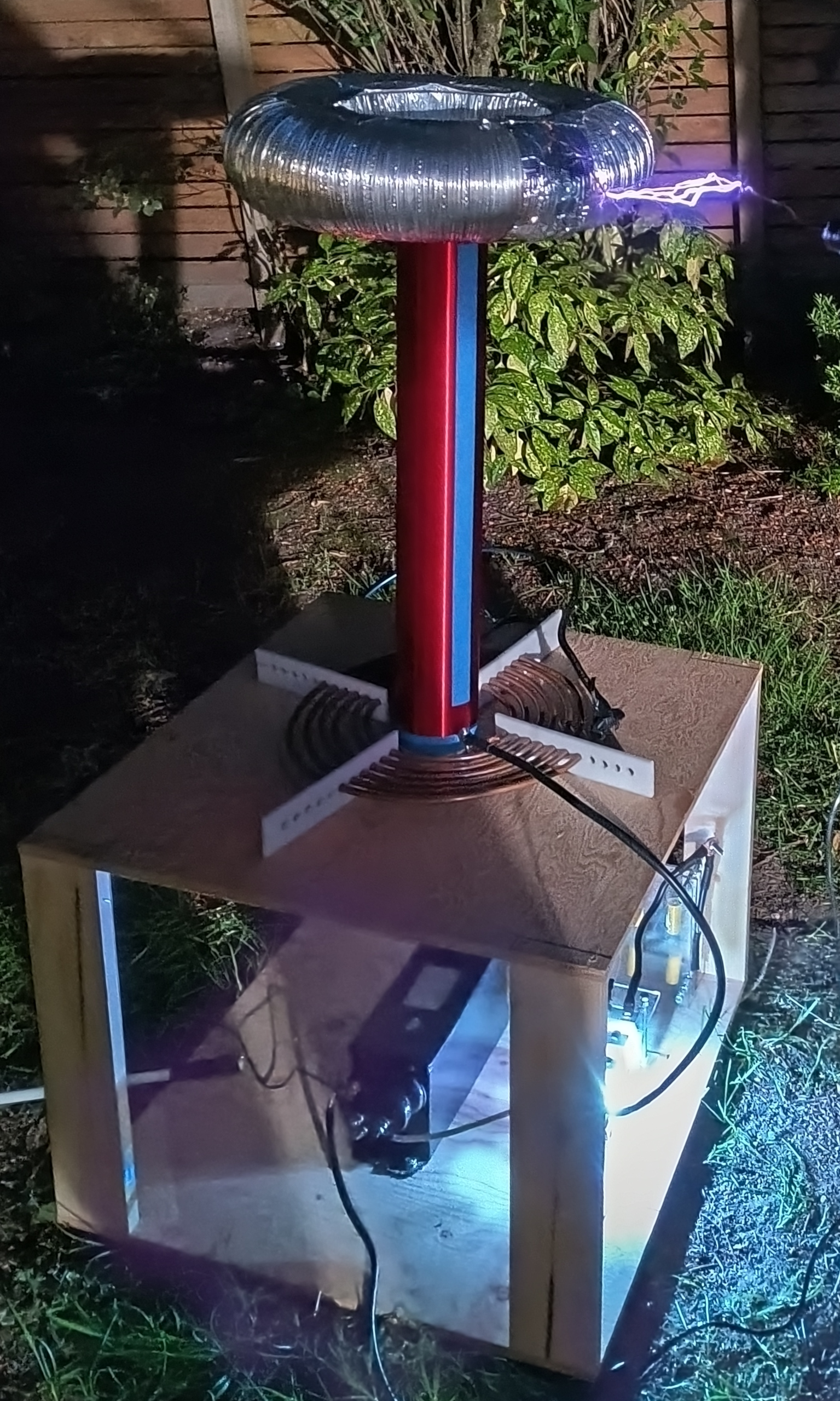
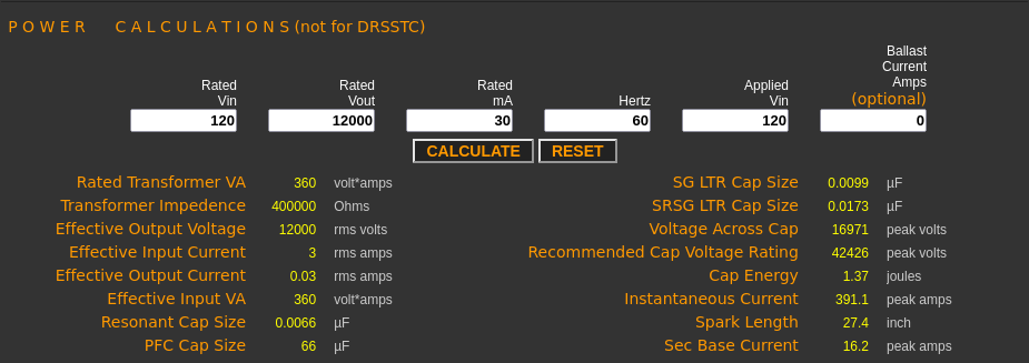
This is a 360 Watt spark gap Tesla coil powered by a 12kV neon sign transformer. It was built as my final for AP Physics sophomore year, and yielded some relatively impressive results. This was my first real high voltage build, my first real Tesla coil. The coil uses a 12kV 30mA neon sign transformer that was purchased off ebay, a 0.0094 micro-Farad MMC capacitor bank that I constructed, a Richard-Quick style spark gap, a primary coil made of 5/16 in copper tubing, a 1000 turn secondary that I bought off ebay, and a toroid made of pie tins and aluminum ducting. It has a resonant frequency of 390kHz and a theoretical voltage of 300-500 thousand volts.
Operation
The coil uses a simple spark-gap design. An LC circuit consisting of the primary coil and the MMC capacitor bank is charged using a 12kV 30mA transformer. When the voltage
of the MMC bank has reached the breakdown voltage of the air between the electrodes of the spark-gap, the spark-gap breakes, allowing the MMC to discharge through the primary
coil. The primary coil acts as an inductor and forms an LC circuit with the capacitor bank, which resonates at a specific frequency, which is dependent on the inductance of
the primary and the capacitance of the capacitor bank. This is the primary resonant frequency.
The oscillating voltage through the primary coil induces a voltage in the secondary coil. The primary coil and secondary coil act as a step up transformer, with a much higher
voltage being induced in the secondary coil. The secondary coil forms its
own LC circuit; The secondary coil is an inductor, and the toroid stores charge, acting as a capacitor with the ground. Thus, the secondary circuit has its own resonant frequency,
the secondary resonant frequency. When the primary circuit induces a voltage in the secondary, it transfers its energy to the secondary coil after a number of oscillations.
These oscillations continue until the voltage of the primary drops to zero, at which point the primary coil with theoretically shut off, allowing the capacitor bank
to recharge and the process to repeat. This process of the primary circuit resonating back and forth until it has transferred all of its energy to the secondary is known as the
primary ringdown. , while the rise in the voltage of the oscillations in the secondary coil is known as the secondary ringup.
However, in practice the primary circuit does not shut off. Because the air surrounding the spark-gap remains ionized and conductive after it has fired,
even after the voltage has dropped to zero in the primary circuit (this is known as the first primary notch)
there is usually enough conductivity through the spark gap that the secondary coil will actually begin to transfer energy back to the primary coil (the secondary ringdown), recharging it until the
secondary voltage drops to zero, (the first secondary notch) and the primary coil then repeats the process of transfering its energy to the secondary. This will go back and forth, often with several
primary and secondary notches until enough energy has
dissipated through the circuit in the form of sparks that the spark gap stops conducting and the primary circuit ceases to resonate, allowing the entire process to repeat. To achieve
the best sparks, you want the tesla coil to have as few primary notches, and thus as few transfers of energy between the primary and secondary each time the primary circuit recharges,
as possible. This is because you want the energy to be dissipated in the form of sparks instead of RF and thermal losses, and so the lesser the number of times the primary and secondary
go back and forth like this, the quicker the energy is being dissipated in the form of sparks. This is where a concept known as quenching comes in.
In a tesla coil, the goal is to match the primary resonant frequency with the secondary resonant frequency. This allows the primary circuit and secondary circuit to resonate,
which allows the tesla coil secondary to maximize its voltage. Tesla coils have relatively weak coupling between the primary and secondary (coupling is the measure
of how quickly the energy is transfered between coils in a transformer. Lower coupling means more oscillations are needed for the coil to discharge, and thus the sparks are
more continous), instead using resonance to maximize the voltage of the secondary. Optimal performance is theoretically reached when the primary and secondary resonant frequencies are
as close as possible, although in practice it is actually better to have the primary and secondary slightly out of tune to reduce system stresses.
Because Tesla coils rely on resonance in order to function, the output voltage of the secondary cannot be found just by calculating the turn ratio of the primary and secondary.
Instead, the maximum voltage of the secondary depends on the amount of energy that is transferred to it. The voltage can then be found using the equation
E = 0.5 * C * V2
Where E is the energy of the system, C is the capacitance, and V is the voltage.
Design
JavaTC was used to design the Tesla coil. JavaTC is a popular tool used to quickly perform the calculations neccessary to design a working Tesla coil that properly resonates and doesn't blow up in your face.
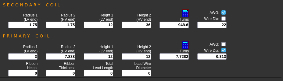
The secondary coil has a 24" tall secondary of approximately 1,000 turns, with a 3.5" radius. It sits about 18" of the ground (12" was used in the JavaTC calculations,
but this isn't super critical).
The primary coil is a spiral that was designed to begin 3.0" from the center of the secondary coil and spiral outwards to a final radius of 7.84", with a total number of turns of
7.73. In the actual design, this was not realized due to some design limitations and human error.
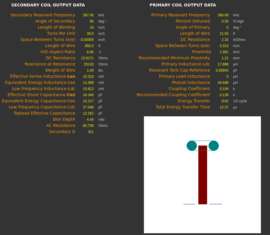
The secondary and primary circuits each have a theoretical resonant frequency of about 390kHz. The secondary uses a toroid with a major diameter of 13" and a minor diameter of 4" as a capacitor, and the primary circuit uses a 0.0094 micro-Farad MMC capacitor bank.
Construction
June 1 2024
Today I began the construction of the capacitor bank. The capacitor bank consists of two rows of ten capacitors each, in parallel with one another, for a total of twenty
capacitors. Each capacitor is 0.047 uF rated at 3,000 volts, for a total rated voltage of 30,000 volts and a capacitance of 0.0094 uF. This matches up well with the
recommended LTR (larger than resonance) capacitor bank size for my setup of 0.0099 uF. Because the voltages in a Tesla coil primary circuit will rise higher than the
output voltage of the transformer, an d can peak at several times this voltage for various reasons, it is smart to have a capacitor bank with a slightly higher capacitance
than the resonant value in order to avoid overloading the system. This puts much less stress on the transformer and capacitor bank and reduces the chances of
damaging the Tesla coil over continous use.
I began construction by marking up the lexan that I bought at the hardware store using a ruler and permanent marker. I used three 50.0 cm x 17.5 cm sheets, 3/16" thick, pancaked together
and held in place using four metal bolts along with a bunch of nuts. After marking everything, I drilled the four 0.25" holes for the bolts in the corners of the three sheets.
I just taped all three together and only marked up the top sheet, drilling through all of them
After this was done, I removed the two other sheets from the pile and drilled the twenty holes for the capacitor leads. I used a small drill bit, around 1/16".
Once the holes were drilled, I began placing the capacitors on the lexan, winding their legs through the holes. Then, I got to soldering the capacitors together,
connecting the leads on the other side of the lexan, through the holes.
June 2 2024
Finished soldering the capacitors together, then soldered the bleed resistors to the capacitor bank. Because the capacitor bank will almost certainly be charged to some
percentage of the breakdown voltage of the spark gap, which is the point at which the spark gap fires and the circuit resonates, there needs to be a way to allow the
capaitor bank to discharge after the circuit has been turned off. By attaching resistors of a relitvely high resistance between the two leads of each of the capacitors,
allowing enough current to discharge the capacitor bank relatively quickly after it has been turned off, but not enough to hinder its performance. In my case, I used
10MOhm (5W?) resistors, between each of the twenty capacitors.
After the capacitors and resistors were soldered together, I added the four bolts and enough nuts to keep the lexan pieces properly spaced apart.
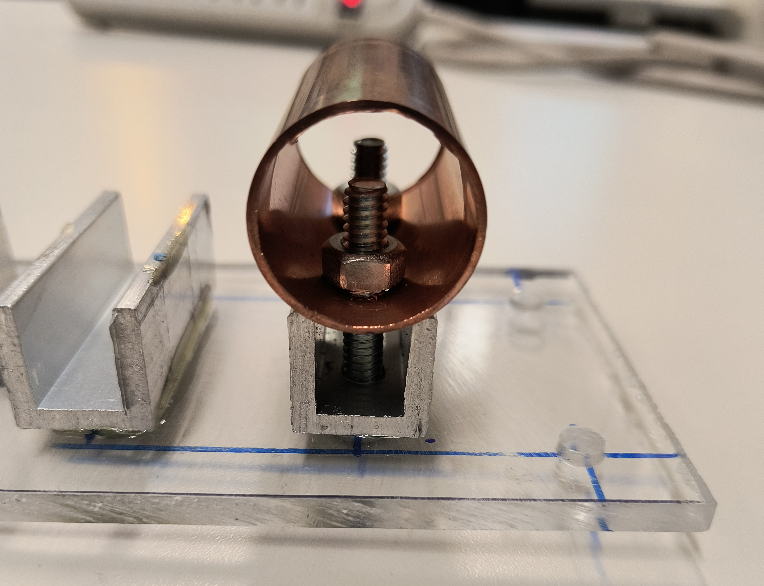
With the capacitor bank almost finished, I began work on the spark gap. The spark gap uses a series of 1" diameter copper tubes as the leads, so I cut nine of those at 2" long.
Then, I put each of them in a vise and marked where I was going to put the holes to mount them, about a (half inch?) from each end of the tube. Each hole was drilled at
at 0.25", through one side, in order to mount the copper tubes.
June 3 2024
This week I finished up the spark gap. I chose to use a static spark gap design based off of "Scot's spark gap". "Scot's spark gap" is a rectangular version of the
Richard-Quick style spark gap. Richard-Quick type spark gaps use multiple electrodes in the form of copper pipes spaced around the inside of a large pipe, so instead
of having just one large gap, you have a bunch of smaller gaps. You essentially divide the spark gap between more electrodes.
Improved Construction of Scot's Spark Gap
The reason for doing this is because of
quenching, which is the term for when the spark-gap ceases to conduct and goes open circuit. When there are more electrodes in the spark gap, the amount of energy
that is being transfered through the spark gap is spread out among these electrodes, and this means that the amount of heat that the spark gap generates is more spread out,
so the heat between each of the electrodes is much less. The reason for minimizing the heat between electrodes is that at the temperatures that the air will be heated to,
conductivity is greatly increased, meaning the air between the electrodes in the spark gap will remain ionized and conductive even after the voltage of the primary circuit
falls below the normal breakdown voltage. If the spark-gap does not quench in time, the secondary coil will actually begin to transfer energy back to the primary
circuit, causing it to resonate back and forth and build up charge in the capacitor, as I mentioned before. To reduce the number of primary and secondar notches, and
maximize the length of the sparks, we need good quenching.
Today I started with marking the two lexan sheets for the spark gap. Each sheet is 8.25"x3.0", and 3/16" thick.
June 4 2024
Drilled four holes in the corners of the two sheets of lexan for the support bolts to go.
June 5 2024
With the lexan sheets now somewhat ready, I cut the seven sections of the aluminum U profile with a jigsaw. The U profile has a 0.75" outside width and height, 0.125" thick. Each piece
is about 2" long (it was somewhat difficult to get a super precise cut with the jigsaw).
Aluminum U Channels after being epoxied to the lexan plates
June 6 2024
All of my components for the spark gap where ready, so today I arranged the aluminum U-channel pieces and epoxied them to the lexan.
June 7 2024
With the epoxy dry, I pried the two halves of the spark gap apart, and marked the positions for the holes through the aluminum U channels. Each U channel has two 0.25" holes
0.5" from both ends to allow two 1.5" bolts through both it and the plexi glass in order to hold the copper pipes. The bolts also act as a point to attach the electrodes to
the spark gap.
June 10 2024
Finished the spark gap today. I put in pilot holes where the bolts will go through the U channels. When I drilled the 0.25" holes, I broke off two of the aluminum channels,
most likely due to the vibration of the drill. I re-epoxied the affected pieces, let that sit for an hour, then continued drilling the rest of the holes.
With the holes done, I fitted all the copper tubes and inserted all the bolts holding them to the aluminum channels. Then, I just added the four support bolts, and the
spark gap was finished.
Did some test runs. At first, I had the two halves of the spark gap misaligned, and I had thought that I had screwed up while building it, that I wasn't careful enough and now
the copper tubes weren't evenly spaced, but then I realized I just needed to rotate one of the halves 180 degrees. Once that was over with, I did some experimenting to find a good gap size.
If the gap is too big, you risk over-volting the capacitor bank or the transformer and blowing something up. The solution to this is to design a safety gap, which is generally a small two electrode
spark gap that is set slightly wider than the breakdown voltage of the transformer, so if the voltage in the system rises higher than it should the circuit can safely discharge and nothing
blows up.
June 11-14 2024
Cut and drilled the pieces of HDPE for the primary coil stand this week. I bought a small HDPE cutting board of Amazon, 8"x10", and cut four 7.75"x1.75" pieces. Then, I drilled
eleven holes in each of these pieces with a 5/16" drill bit to feed the 5/16 copper tubing through.
The holes are positioned in intervals of 5/8 of an inch, and sit 1.0" from the bottom of each of the pieces to align with the bottom of the secondary coil.
The reason for using HDPE is that it is a very good insulator, which is something that is important to have for the best performance of the primary coil. Materials like wood don't always
act like good insulators when you are dealing with hundreds of thousands of volts, as they can absorb moisture, so HDPE is great if you want a reliable insulator. The downside is its not as
convenient to work with as wood.
June 15 2024
Today I finished up the capacitor bank. In order to do so, I needed to attach two leads on both ends of the capacitor bank to actually connect both rows of the capacitors and to add a
terminal for the capacitor bank to hook up with the rest of the circuit. I used two ~6 inch pieces of the 4 guage wire I bought at the hardware store. Beforehand, I crimped on a
0.25" diameter 4 gauge car batter terminal to each of these pieces, and stripped two sections of the insulation from the wire to solder it to the leads of the two end capacitors
on both sides.
June 16 2024
Built (technically my Dad did most of the work on this one, but I designed the thing and helped out with it) the frame for the coil,
and mounted the NST and capacitor bank.
The frame is constructed from two 2'x2' 0.5" thick sheets of plywood with four 1"x4" 17.5" long legs sandwiched in-between. It's a little heavy, next time I won't make my frame as large,
or I will construct it from a different material.
With the frame complete, I then marked everything out on the frame and decided where exactly to put all the components. With everything planned, I mounted the capacitor bank and the NST.
As for the capacitor bank, I drilled some holes in two of the legs of the frame, then fited the four bolts holding the bank together through these holes and fastened them using some
nuts. With the NST, I measured out where the center of the frame was, then drilled some holes in the bottom in the position of the holes in the NST mounting plate, then used some thick
3/8"? in bolts to fasten it. Because there are no legs on the frame, and I only put on two bolts, now the whole thing is quite wobbly, which is something I will need to fix.
I also started winding the primary coil. I tried just winding the copper tube through the HDPE supports, but realized I had made the holes too small. It turns out making
the holes the same diameter as the tubing you are trying to put through it is a horrible idea, so I re-drilled the holes with some non-standard drill bit I got at the hardware
store, something around but a little less than 3/8". I did manage to wind the tubing through the supports, but when I was thoroughly confused how I had ended up with four turns
even though I had more than enough copper tubing, I realized it wasn't enough to just thread the copper tubing through, you actually had to ensure yourself the spiral diameter was the right
size, and that this wouldn't happen magically on its own. Somehow I thought the spiral would magically have the correct diameter if I just randomely threaded the tubing through,
this is not the case. During one of my attempts to thread the coil, I thought I had everything right, so I cut the copper pipe, before realizing that what I was attempting to do would
not work and I had actually cut the coil too short. I decided to table it for later.
June 18 2024
Finished winding the primary coil. This is the part of the coil that I was the most unsuccessful with, mainly because I underestimated just how difficult it was going
to be to wind the primary coil. It took me several tries until I found a working strategy, by threading the outside hole first and working on the spiral inwards
to outwards.My current primary coil is approximately seven turns, instead the minimum of eight that I was hoping for in order for it to be in tune, because I cut it short, as I mentioned before.
With the coil threaded through,
I clamped on a 1/0 guage car battery ring terminal, again with a 0.25" hole, to the inside end of the spiral. Its not a very good spiral, but it works allright. I have every
intention of making a new primary coil, which will be somewhat expensive given the price of copper pipe, but neccessary for optimal performance. Also, instead of just drilling holes like
I did with this one, I am going to add slots. I ignored all of the resources telling me that simply drilling holes and threading the pipe through is insanely difficult, and I have
come to regret this decision. I may keep the current HDPE pieces and just add some slots, as they are in pretty good condition, albiet a bit curved from the pressure put on them while
cutting them out.
Mounted the spark gap to the frame of the Tesla coil. I decided to put it front and center, lined up with the NST, as it is in parallel with the transformer. Driled some holes
in the bottom piece of plywood, and bolted the legs of the spark gap down. You can adjust the spark gap by moving the bolts that hold the bottom plate up, although it is a little
tedious with the bottom piece of the spark gap so close to the plywood. I could some larger legs for the spark gap.
Finished up the secondary coil as well. I bolted together two 7 inch pie tins, one facing up and one facing down, and wrapped the aluminum ducting I bought around the two pie tins.
Cut the ducting to the proper size, and taped the two ends together with some aluminum tape. For some reason, the aluminum tape I bought is not very strong, and the toroid
has broken apart on multiple occasions.
When I was content with the toroid, I unwinded a bit of the secondary wire on the top, sanded it down to remove the enamel, and used some aluminum tape to attach it to the toroid.
I also winded the wire around the bolt holding the pie tins together, to ensure there is as much conductivity as possible. Then, I placed the toroid over the secondary, and epoxied it to
the pipe. The toroid is a little flimsy, it wobbles around a bit on the secondary, and the aluminum ducting keeps breaking apart, but other than that it works well.
Since I didn't want to permanently attach my secondary coil to the frame, I was trying to find reliable way to attach the secondary to the frame without directly gluing it on. I ended up
using a small piece of pvc that looks like a drain cover of some kind. has a 3.0" inner diameter, and is an inch or two tall, and is perfect for mounting the secondary to, as it fits snugly inside
the pvc pipe that the secondary is wound around, so I epoxied that to the center of the top sheet of plywood.
June 19 2024
Finished Mk. 1 today!
I completed all the wiring and the grounding. First, I made the mountable tap. In order to tune the Tesla coil, I needed to a way to effectively make the primary coil variable in size, and
the way to do that is by making one of the connections to the primary coil movable. By soldering one of my thick 4 guage wires to a fuse holder I got off the internet, I was able to accomplish
this. The fuse holder is about the right size that it can fit the 5/16" copper tubing in its jaws. It isn't perfect, and it comes off pretty easily, but it works. By moving the fuse holder to different
locations along the primary, you can chose how much of the primary coil is effectively in the circuit, and as the inductance depends on how much of the primary you are using, you can
change the resonant frequency by changing the mount point. This is how the Tesla coil can be tuned, by changing the position of the tap until the best resonance is achieved.
The tape on the toroid decided to fail, so I got some new alumium tape from the hardware store, and used that instead. It worked better, although several weeks later I came into the garage to
find the toroid broken yet again, the aluminum ducting lying on the floor.
Unwound some of the wire on the bottom part of the secondary, sanded off the enamel, and used some aluminum tape to make an RF ground. Punched a hole through this to fit a 0.25" screw, then made
my grounding rod. I just drilled a 0.25" hole in a 1' section of 1" diameter copper pipe I got at the hardware store and bot a bolt through, with enough room to put some ring terminals on.
The ground rod connects to the secondary RF ground using a section of 4 gauge wire with car battery ring terminals on either end. I would have made the ground wire longer, as it is only
a couple feet, but I ran out of wire and that stuff is expensive. You hammer the ground rod into the ground (believe it or not) in order to provide a good HV ground for the secondary coil.
Mains ground is insufficient, and just stupid. You do not want to be running hundreds of thousands of volts through the ground of your AC mains, and it wouldn't work well regardless.
At these voltages, you need to use a metal tube of some kind to get proper grounding. Running half a million volts through some flimsy 12 gauge house wire to half inch wide ground rod will
not give you good grounding because of the skin effect. At frequencies like these, at several hundred thousand Hertz, the density of the electric current is much higher near the surface
of the conductor than it is deeper within the conductor, due to eddy currents. That is, most of the electrons are concentrated on the outer rim of the conducter. Because of this, You are going to get the best performance
with a conductor that accomodates these conditions, such as a copper tube, where the radius of the conductor is quite large.
(Eddy currents are loops of electric current that are induced by a changing magnetic field. Since high frequency AC will create a pretty good changing magnetic field, eddy currents
are induced, and these essentially push the current density outwards.)